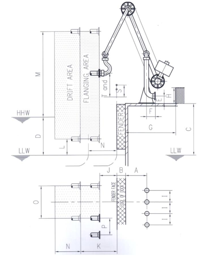
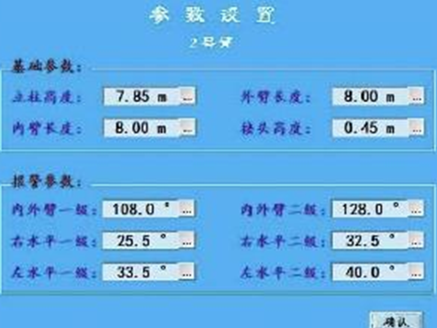
Meteorological parameters and other on-site conditions are determined
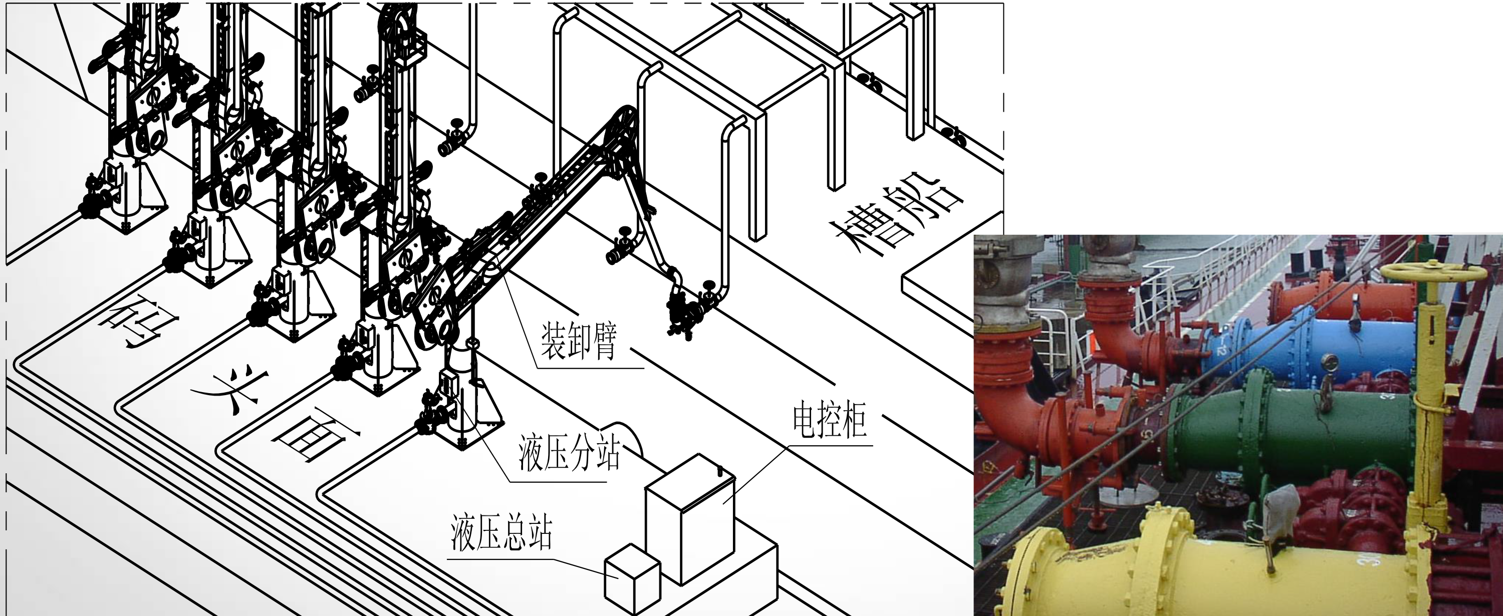
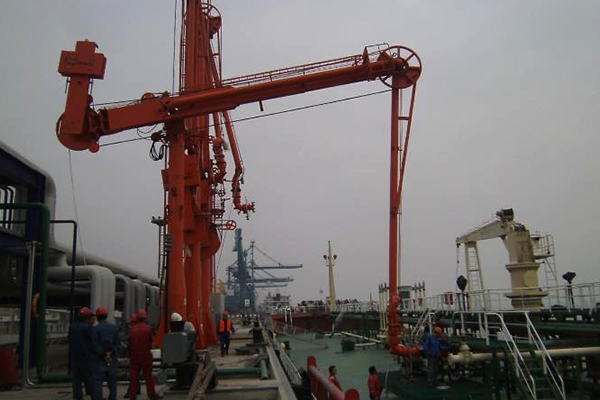
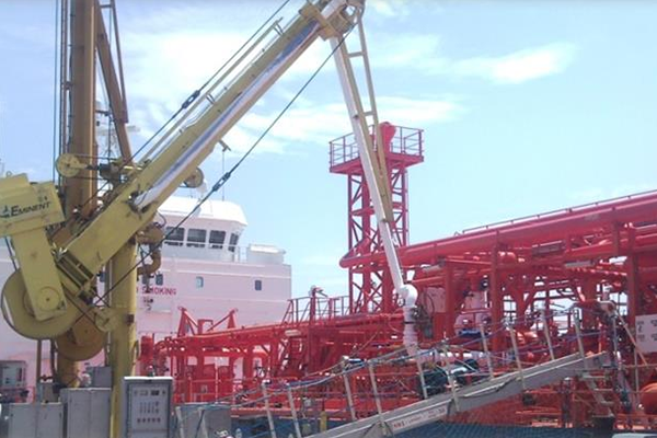
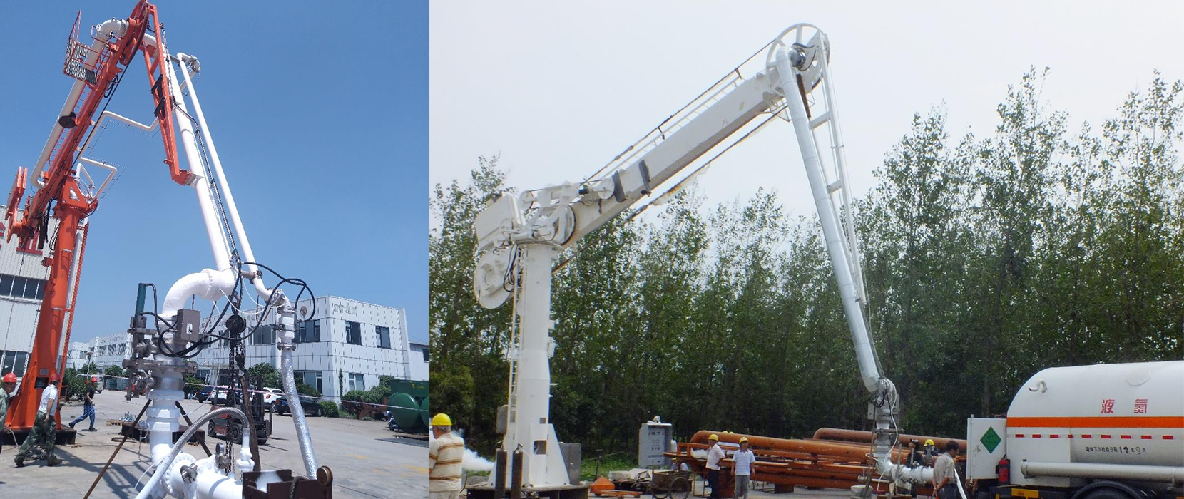
Arrangement of loading and unloading arms on the dock
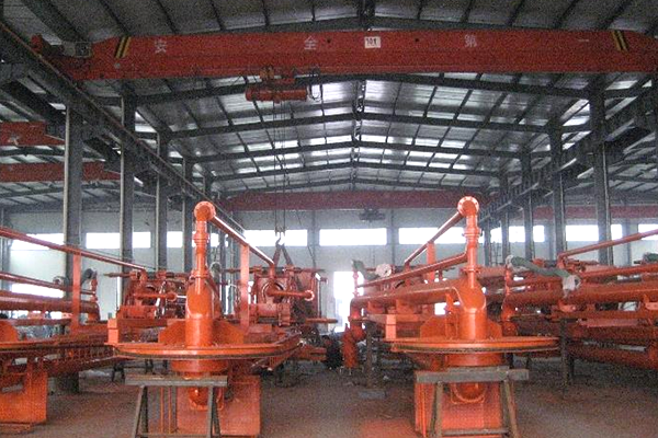
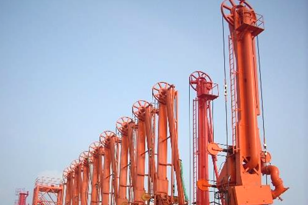
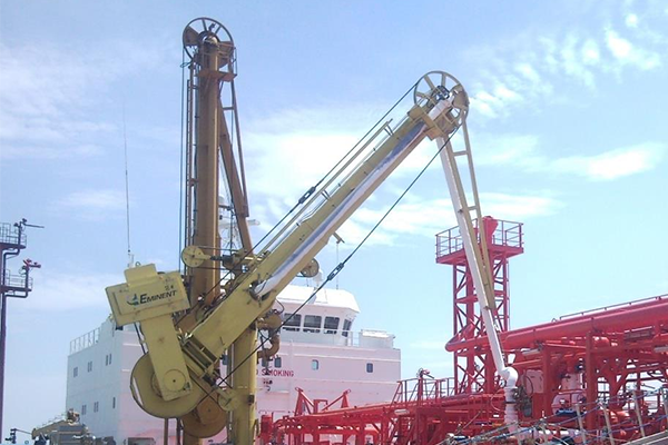
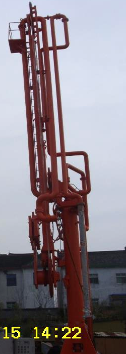
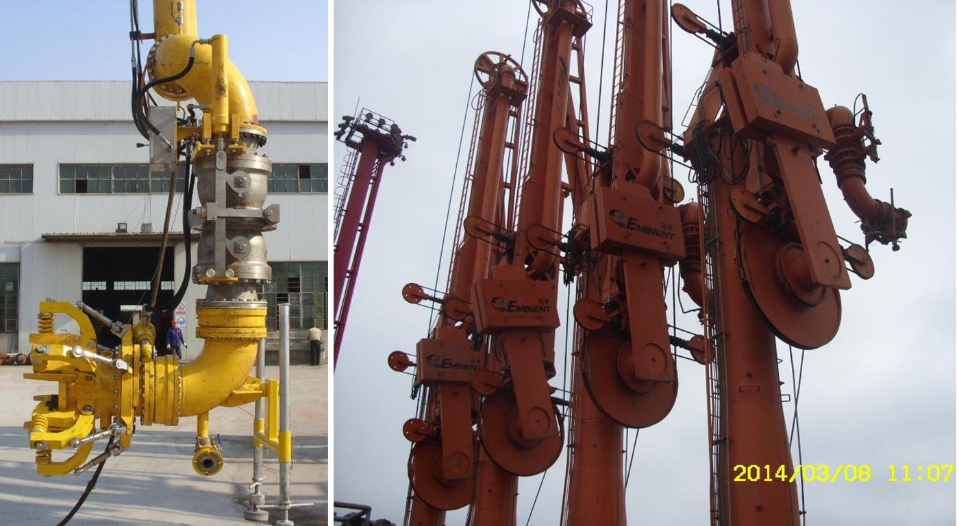
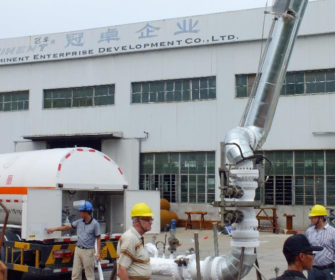
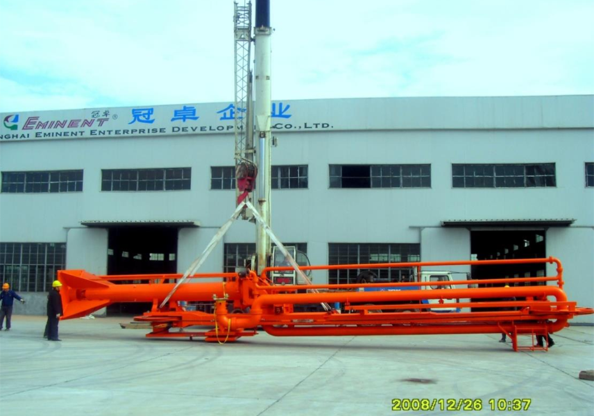
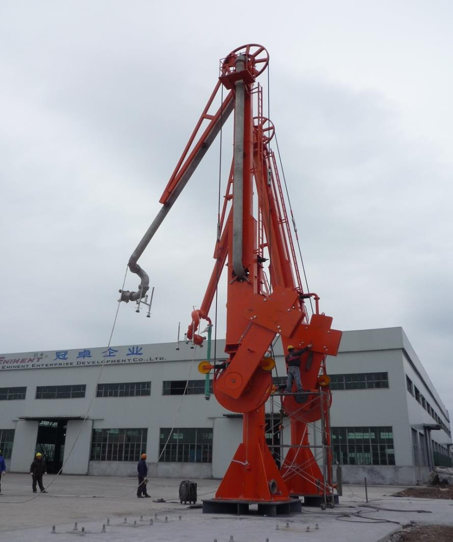
Application introduction of marine loading and unloading arm (fixed type)
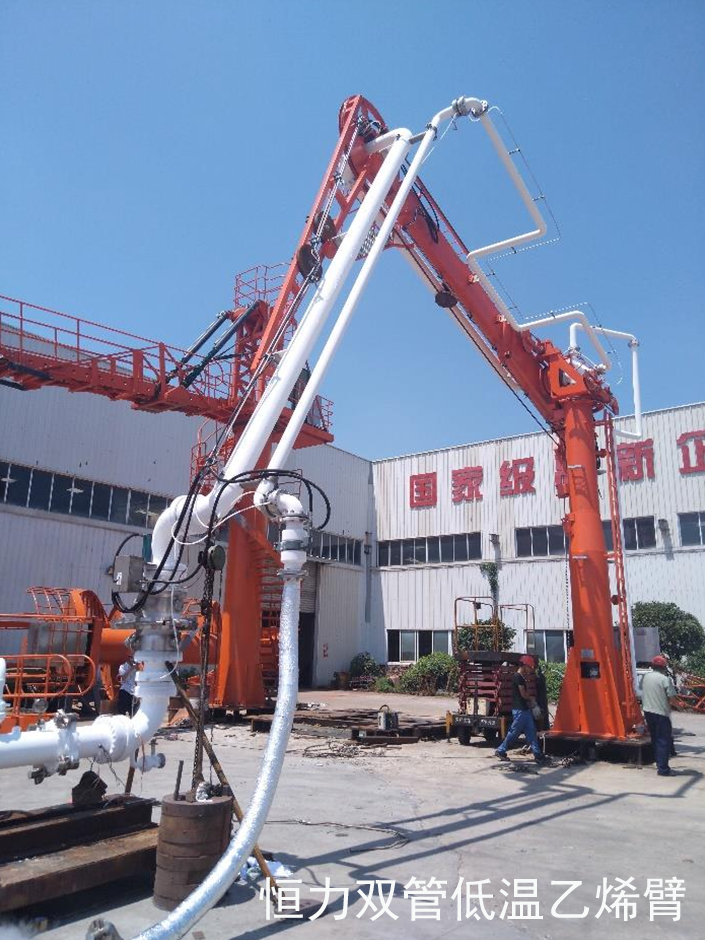
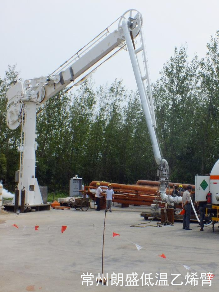
Low temperature ethylene marine loading arm
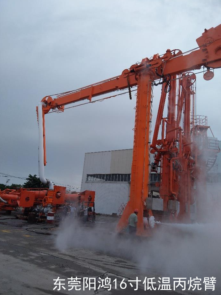
LNG ship loading and unloading arm
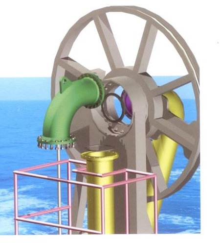
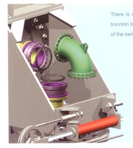
Rotary joint maintenance and care
Upper sheave part
Shaft box part
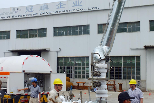
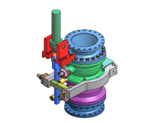
2. Introduction to Emergency Release System (ERS)
Emergency release system components
The emergency release system (ERS) mainly consists of three parts: emergency release device, electrical control system and hydraulic control system.
Double ball valve emergency release device
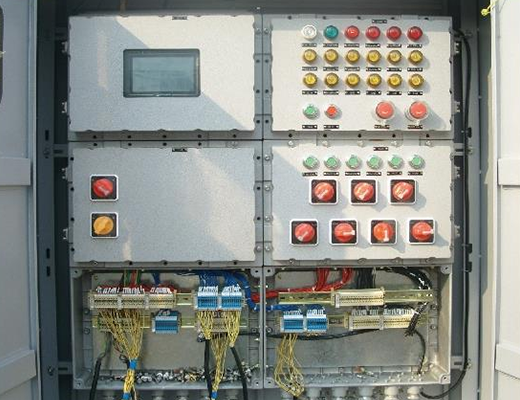
Electrical control system
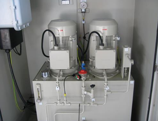
Hydraulic pump station
Control valve box
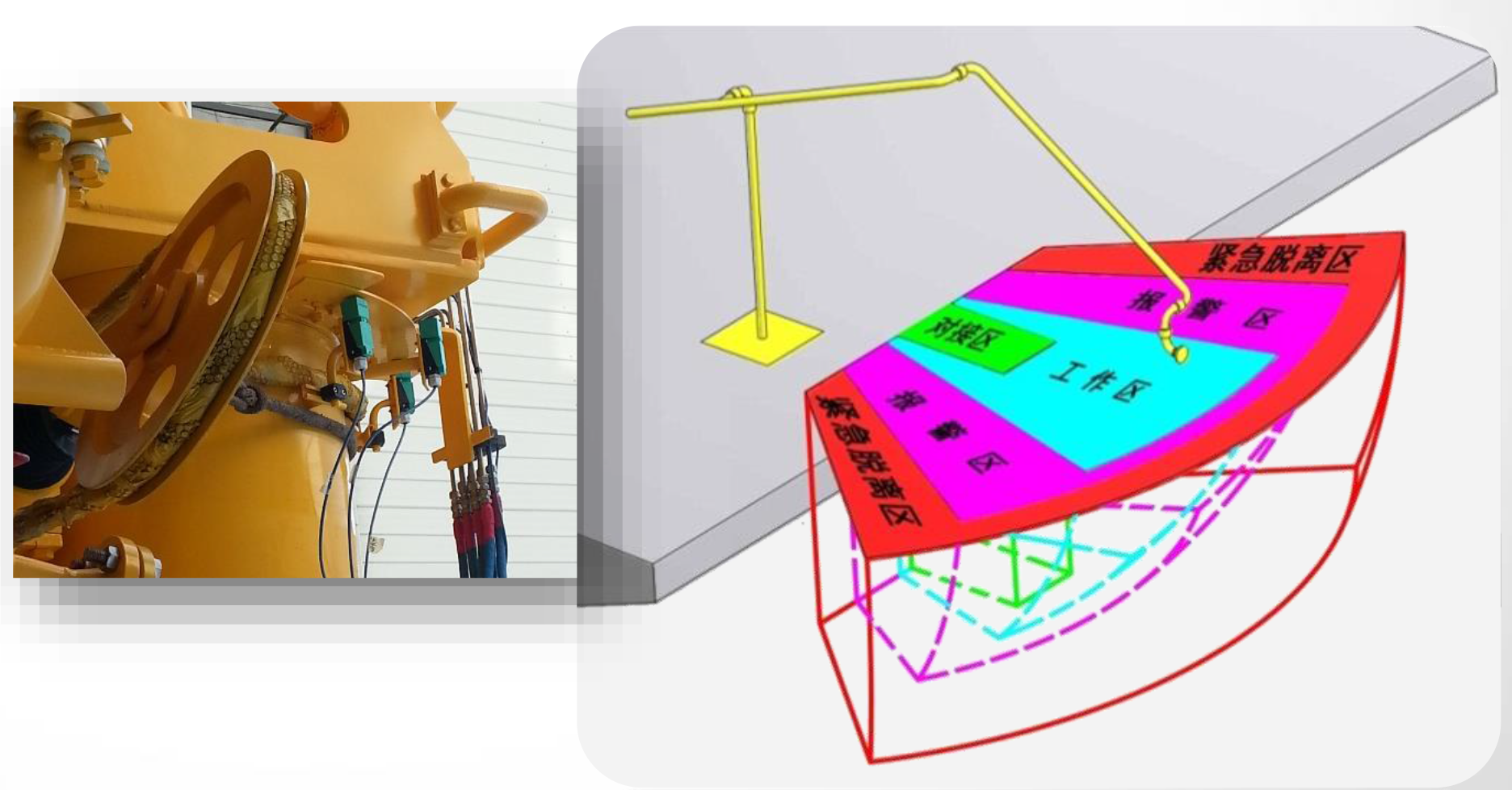
Emergency release installation position
Emergency release system activation conditions
When the tank ship drifts out of the specified envelope, the system will automatically start to close and separate the upper and lower valves of the emergency release device within the set time to achieve safe separation of the loading and unloading arm and the tank ship.
In special circumstances, when the tank ship leaves the dock, the emergency release must be manually activated on the electrical control cabinet to close and separate the upper and lower valves of the emergency release device to achieve safe separation of the loading and unloading arm and the tank ship.
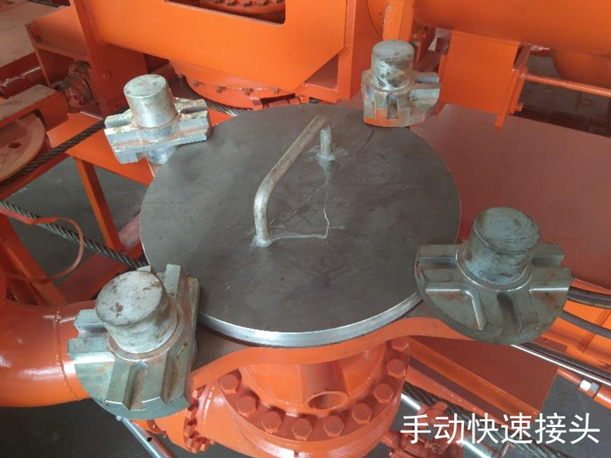
3. Quick Connector (QC/DC) Introduction
• Quick connectors (QC/DC) are divided into two types: manual quick connectors and hydraulic quick connectors.
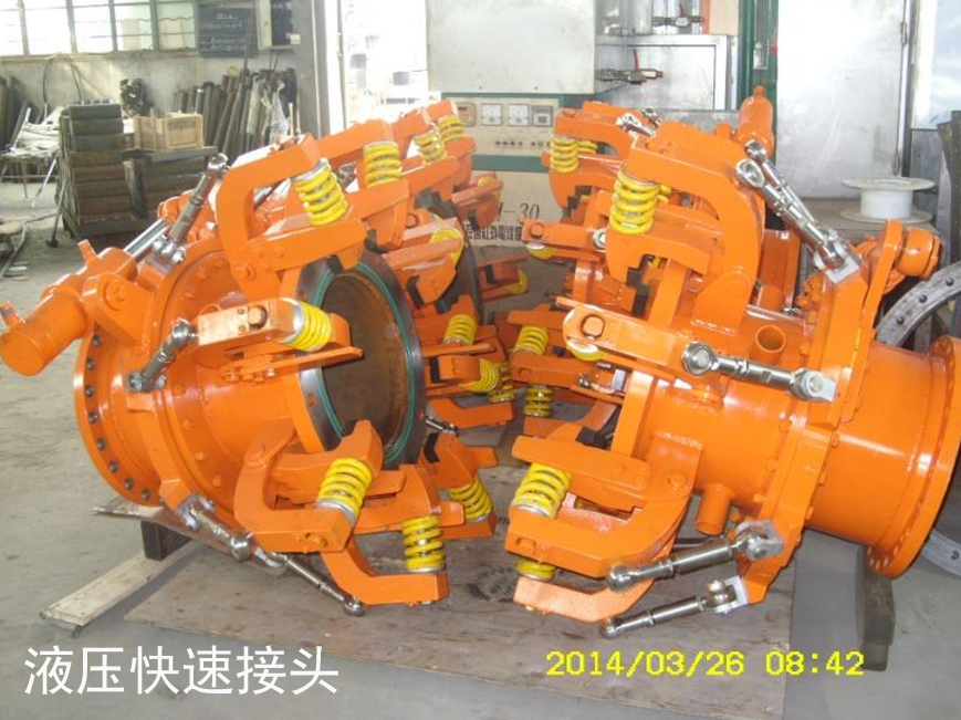
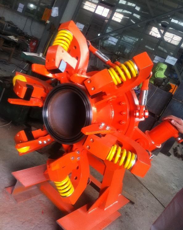
Hydraulic quick connector (EQC/DC) introduction:
• Features of hydraulic quick connectors: The hydraulic system is used as the power source; the main power actuator of the equipment adopts the national hydraulic general component - hydraulic cylinder. The hydraulic cylinder is a mature mechanical product. Its performance and advantages have been widely recognized in the machinery industry. Therefore, its use in this equipment can greatly improve the overall stability of the equipment, improve its performance, and reduce the failure maintenance rate.
• The system adopts PLC logic control to make the control system stable, reduce the high failure rate of old relays and the difficulty of fault finding, and make maintenance more convenient. The remote control system can realize long-distance control and improve work efficiency.
• Automatic control of connection and separation is adopted to change the traditional manual connection method, thus greatly improving the reliability and flexibility of operation. It also greatly reduces the labor intensity of operators and improves work efficiency.
• Pipe flanges can be made of the corresponding standards as required, and can be docked and installed on both new designs and old oil transfer arms, greatly improving the applicability of the product.
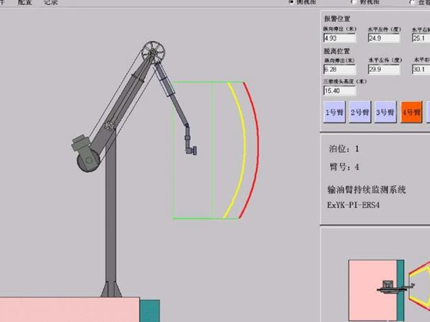
Real-time location monitoring system
Accident during loading and unloading arm operation
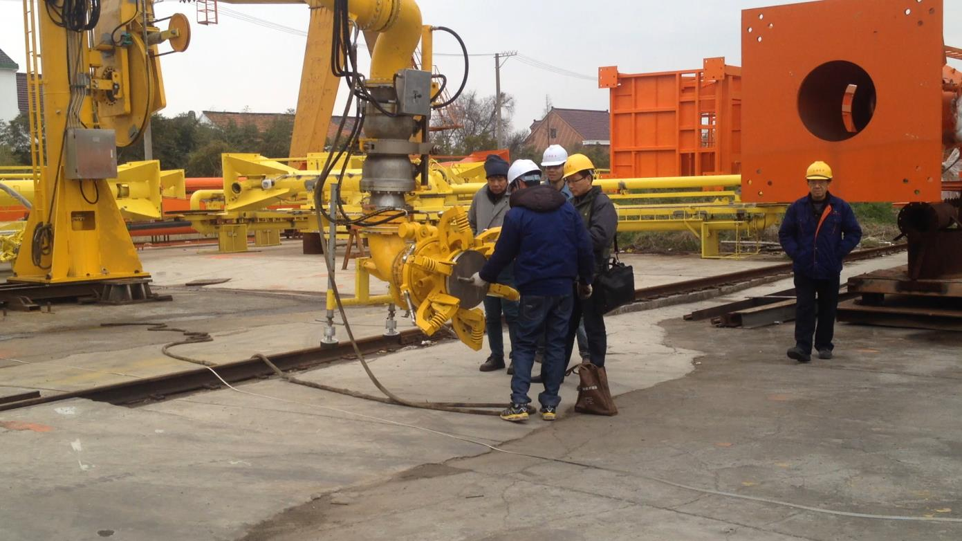
Hydraulic QC/DC ship acceptance test
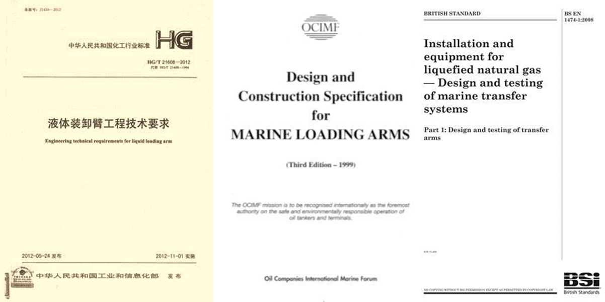
III. Explanation of current standards for fluid handling equipment
HG/T 21608 "Engineering Technical Requirements for Liquid Loading and Unloading Arms"
internationality
OCIMF《Oil Companies International Marine Forum》
BS EN1474《LNG loading and unloading arm design and testing》
Emergency Release System (ERS)
HG/T21608-2012 "Liquid Loading and Unloading Arm Engineering Technical Requirements" Article 4.7.1
The emergency release system (ERS) should meet the requirements of environmental protection, operator safety, and protection of dock loading and unloading arms and tank ship equipment. Liquid loading and unloading arms that transport crude oil, light oil, liquefied hydrocarbons, flammable liquids, corrosive media, toxic liquid media or cryogenic liquid media should be equipped with a hydraulically operated emergency release system.
Emergency Release System (ERS) Release Test
1. Factory test
Article 4.13.6 of 21608-2012 Technical Requirements for Liquid Loading and Unloading Arms stipulates: After the strength and sealing performance tests are passed, a separation test is conducted for 5 consecutive times. A real liquid separation test is added according to the owner's requirements.
2. Field Test
Article 4.7.10 of 21608-2012 "Technical Requirements for Liquid Loading and Unloading Arm Engineering" stipulates: The emergency release device shall be subject to a system test every six months to check the reliability of the clamping mechanism and the entire system.


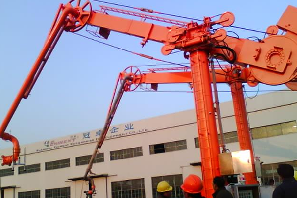
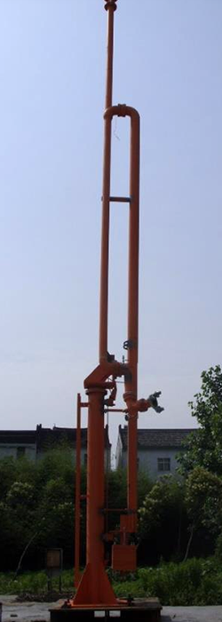
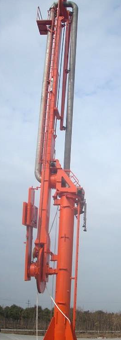
 Ship loading and unloading arm structure