

Crane pipe (land-based fluid loading and unloading arm)
Retail Price
Market price
Weight
Inventory
隐藏域元素占位
Crane pipe (land-based fluid loading and unloading arm)
Classification:
Reservoir Products
- Product Description
-
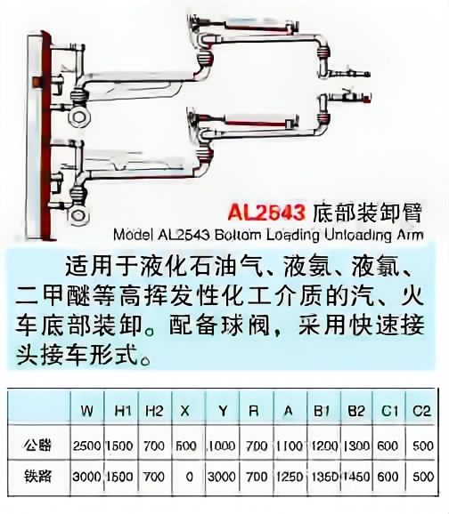
The reason why the crane hose is so important is that it has flexible rotation, good sealing, and high technical content. In the filling or unloading of liquefied hazardous chemicals such as liquid chlorine, liquid ammonia, liquid alkali, dimethyl ether, liquefied petroleum gas, and LNG tankers, it can achieve safe and environmentally friendly transportation of fluid media, and eliminate the casualties, economic losses, safety and environmental protection accidents caused by the frequent explosion of hoses in the filling of liquefied hazardous chemicals.
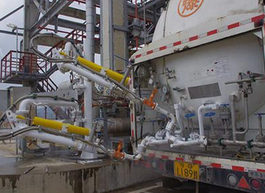
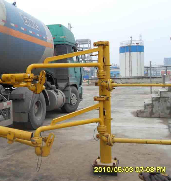
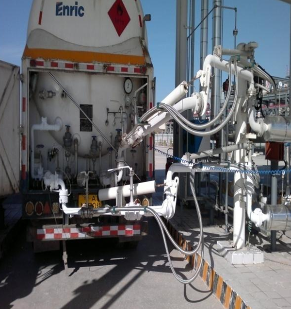
Typical loading and unloading truck crane pipe real picture
Introduction to Crane Pipe (Fluid Loading and Unloading Crane Pipe)
The land-based fluid loading and unloading arm is a special equipment that is connected in series with a pipe using a rotating joint that has multiple characteristics such as flexible rotation, good sealing, and the ability to adapt to relatively harsh environments. It is used to transfer liquid or gas products between the loading platform and the road/rail tank car.
- For tank trucks with open tops and sealed tops or bottom loading and unloading operations;
- During loading and unloading, the tank truck moves with the tank truck within its normal moving range.
——Can be operated manually or pneumatically:
——Balance can be achieved through spring cylinder:
——There are various auxiliary facilities available for selection to achieve safe operation or environmental protection;
——The pipeline can be made of carbon steel, stainless steel or PTFE-lined carbon steel;
——The nominal diameter of the liquid phase pipeline is 2", 3", 4", 6" and other diameters are also available. The nominal diameter of the return air pipeline is t", 2" 3", etc.
——The design temperature range is -196℃=+300℃:
——Design pressure is PN1 OMPa = PN10MPa
——Land-based fluid loading arms can be divided into two types: top loading arms and bottom loading arms
The crane pipe is a piping system composed of multiple rotating joints, multiple sections of pipes with the same or different diameters and different lengths, pipe fittings, ball valves, flanges, quick-release joints, loose flanges, anti-static devices, spring cylinder balancing devices and quantitative loading control systems, which can enable a group of pipes to complete specified movements in three-dimensional space.
● According to the location of the crane during loading and unloading, it can be divided into two categories:
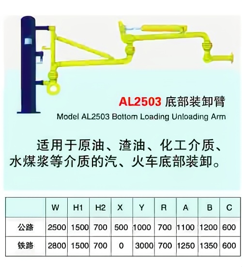
● (1) Loading and unloading crane pipes at the bottom of tank trucks
● (2) Loading and unloading crane pipes on the top of tank trucks
Adaptable medium:
Liquid ammonia, liquid chlorine, liquid alkali, liquefied petroleum gas, dimethyl ether, alcohols, acids, alkanes, oils and other liquids and gases, LNG media.
Applicable models:
Automobile tank cars, train tank cars, tank ships, steel cylinders, etc.
Optional accessories:
Ball valves, quick-release connectors, loose flanges, emergency breakaway valves (domestic or imported), quantitative loading control systems (including filters, flow meters, regulating ball valves, pressure gauges, temperature and pressure transmitters), etc.
Manufacturing standards:
People's Republic of China HG/T 21608-96 "Liquid loading and unloading arm"
Equipment Specifications:
The nominal diameter range of liquid phase pipelines is DN50-DN200, and the nominal diameter range of gas phase pipelines is DN25-DN100.
Design temperature: -196℃~+300℃
Design pressure: 1.0-10MPa.
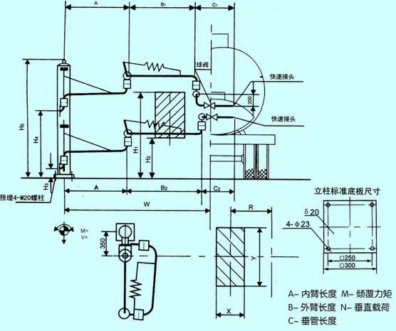
Typical structure of bottom loading and unloading crane
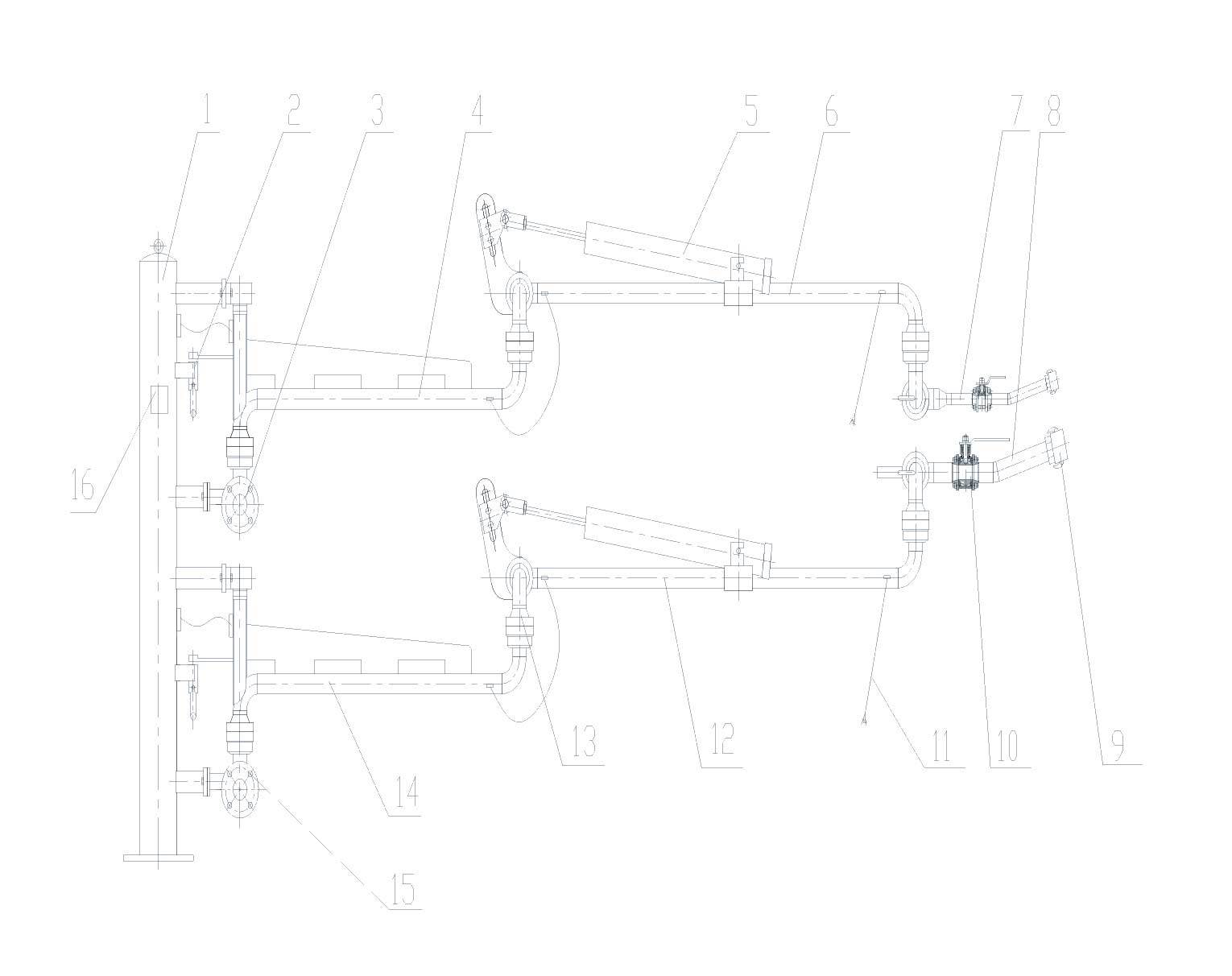 The composition of the bottom loading and unloading crane pipe:
1. Column
2. Inner arm locking device
3. Gas phase inlet flange assembly
4. Gas phase inner arm
5. Spring cylinder balancing system
6. Gas phase outer arm
7. Gas phase outrigger
8. Liquid phase outrigger
9. Quick connector
10. Ball valve
11. Anti-static device
12. Liquid phase outer arm
13. Intermediate connector
14. Liquid phase inner arm
15. Liquid phase inlet flange assembly
16. Nameplate
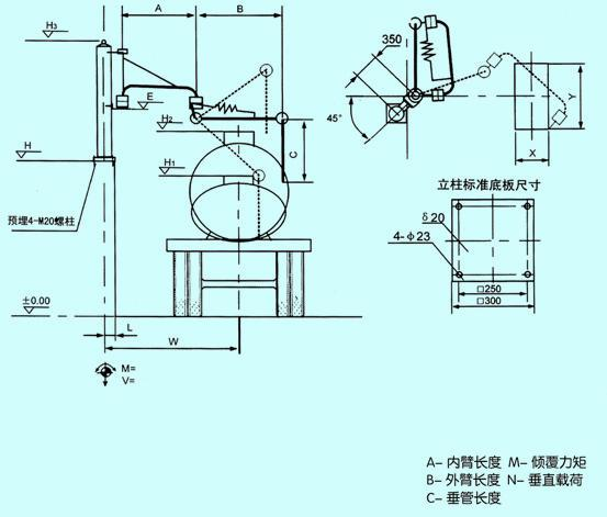
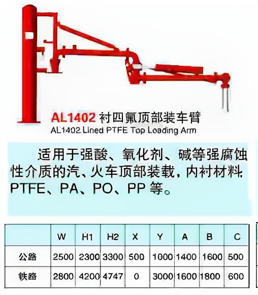
Typical structure of top loading crane
The composition of the top loading crane pipe:
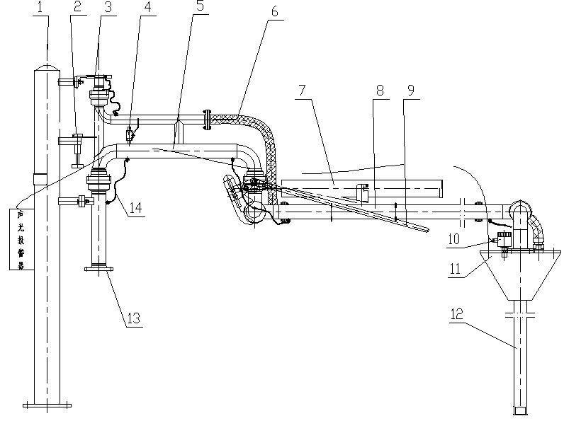 1. Column
2. Lock the inner arm
3. Gas phase interface
4. Vacuum interrupter
5. Inner Arm
6. Air return metal hose
7. Spring cylinder
8. Outer Arm
9. Lock the outer arm
10. Liquid level probe
11. Conical sealing cap
12. Vertical pipe
13. Liquid phase inlet
14. Static Conductive Belt
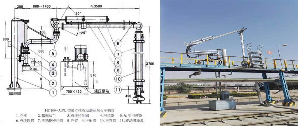
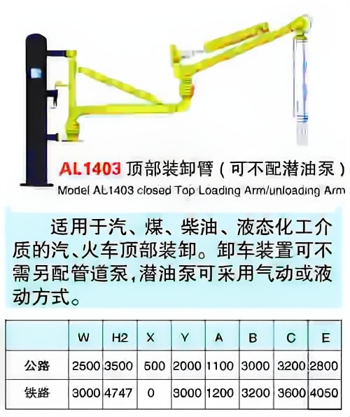
Main categories of top loading crane pipes
According to the purpose of use, the top crane can be divided into two categories:
The loading crane on the top of the tank truck (as shown above), the unloading crane on the top of the tank truck with a submersible pump (as shown below)
Main operation mode of top loading crane pipe
According to the operation mode, crane pipes are mainly divided into three categories:
Manual operation, hydraulic operation, pneumatic operation
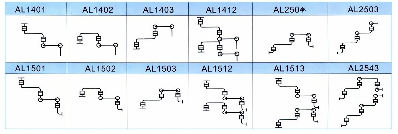
Crane pipe model description
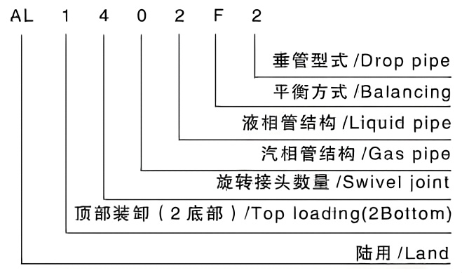
Main models and structural forms
Advantages of crane pipe
▲ Safety and environmental protection: It eliminates safety and environmental accidents such as hose bursting, ensuring the safety of loading and unloading.
▲ High efficiency: The loading efficiency is improved. It used to take 2 to 3 hours to load a car, but now it only takes about 1 hour.
▲ Economical: The service life of the hose is half a year to one year, while the service life of the loading and unloading arm can reach more than 10 years.
▲ Convenience: easy installation, easy operation, easy maintenance, and minimal repair work.
Material selection for loading and unloading arms
● Generally, non-corrosive petrochemical liquid materials usually use high-quality carbon steel pipes.
● To keep the petrochemical liquid pure and prevent rust from mixing in, the loading and unloading arm pipelines should be made of stainless steel pipes; if the liquid material is used directly in the food industry, the loading and unloading arm pipelines should also be made of stainless steel.
● Materials commonly used for loading and unloading arms of corrosive acidic and alkaline materials
● Nitric acid: Stainless steel pipes or plastic-lined pipes should be used for loading and unloading arms. If the vertical pipe is inserted into the tank truck for a long time, aluminum pipes can be used for the vertical pipe liquid.
● Glacial acetic acid: Acid-resistant stainless steel pipe material (316L) can be used
● Sulfuric acid: 98% sulfuric acid and fuming sulfuric acid are made of high-quality carbon steel pipes.
● Dilute sulfuric acid (below 80%): Use steel-lined PTFE pipes, steel-lined PVC pipes, steel-lined PP pipes, etc. If the vertical pipe needs to be inserted into the tank truck, PVC pipes, PP pipes, PTFE pipes or fiberglass pipes can be used to insert the vertical pipe.
● Hydrochloric acid: The material selection is basically the same as that of dilute sulfuric acid.
● Caustic soda solution (normal temperature): The loading and unloading arms are made of high-quality carbon steel pipes.
Structural type selection of loading and unloading arms
1. For loading and unloading low-volatile, non-hazardous liquid media, open type can be selected;
2. When loading and unloading volatile media whose volatile gases have recovery value, a closed form with a gas circuit can be selected;
3. When loading and unloading flammable, explosive, liquid media that are prone to static electricity accumulation, pollute the environment, and are harmful to the human body, choose a form with a gas circuit and a sealing cap, install an anti-static system, and use an automatic telescopic sleeve with a diverter cap.
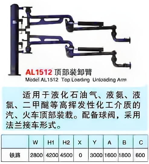
4. For loading and unloading of liquefied gas media such as liquid ammonia, liquefied gas, and dimethyl ether, use a double-tube closed form; the car uses a bottom arm, and the tank car interface uses a quick-release connector; the train uses a top arm, and the tank car interface uses a loose flange.
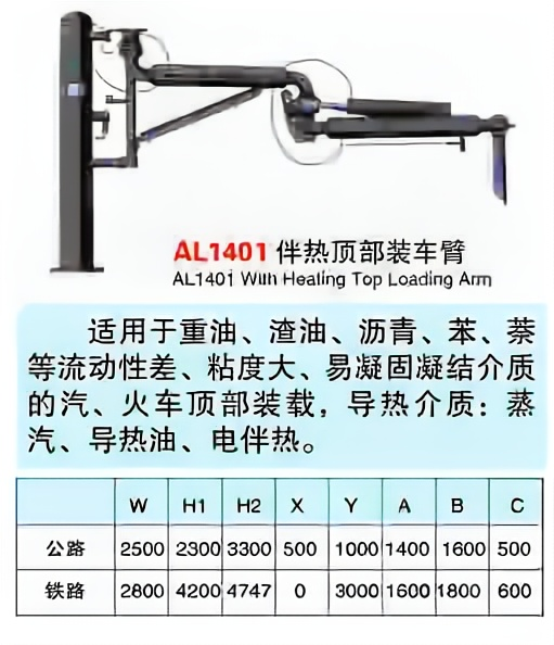
Principles for selecting heating methods
● When the freezing point of the liquid material being loaded and unloaded is higher than the lowest ambient temperature, heating measures should be taken during the storage and transportation of the liquid material being loaded and unloaded.
● There are three heating modes for loading and unloading arms:
Steam heating, thermal oil heating, electric heating
Selection or purchase of loading and unloading arms
● When confirming the selection of loading and unloading arm, the user survey form provided by the manufacturer should be filled in. The manufacturer should meet the design requirements and provide the user with the installation dimensions and related parameters of the loading and unloading arm.
Top loading arm envelope diagram
Bottom loading arm envelope diagram
Typical structure introduction


Application of cryogenic loading skids in LNG stations
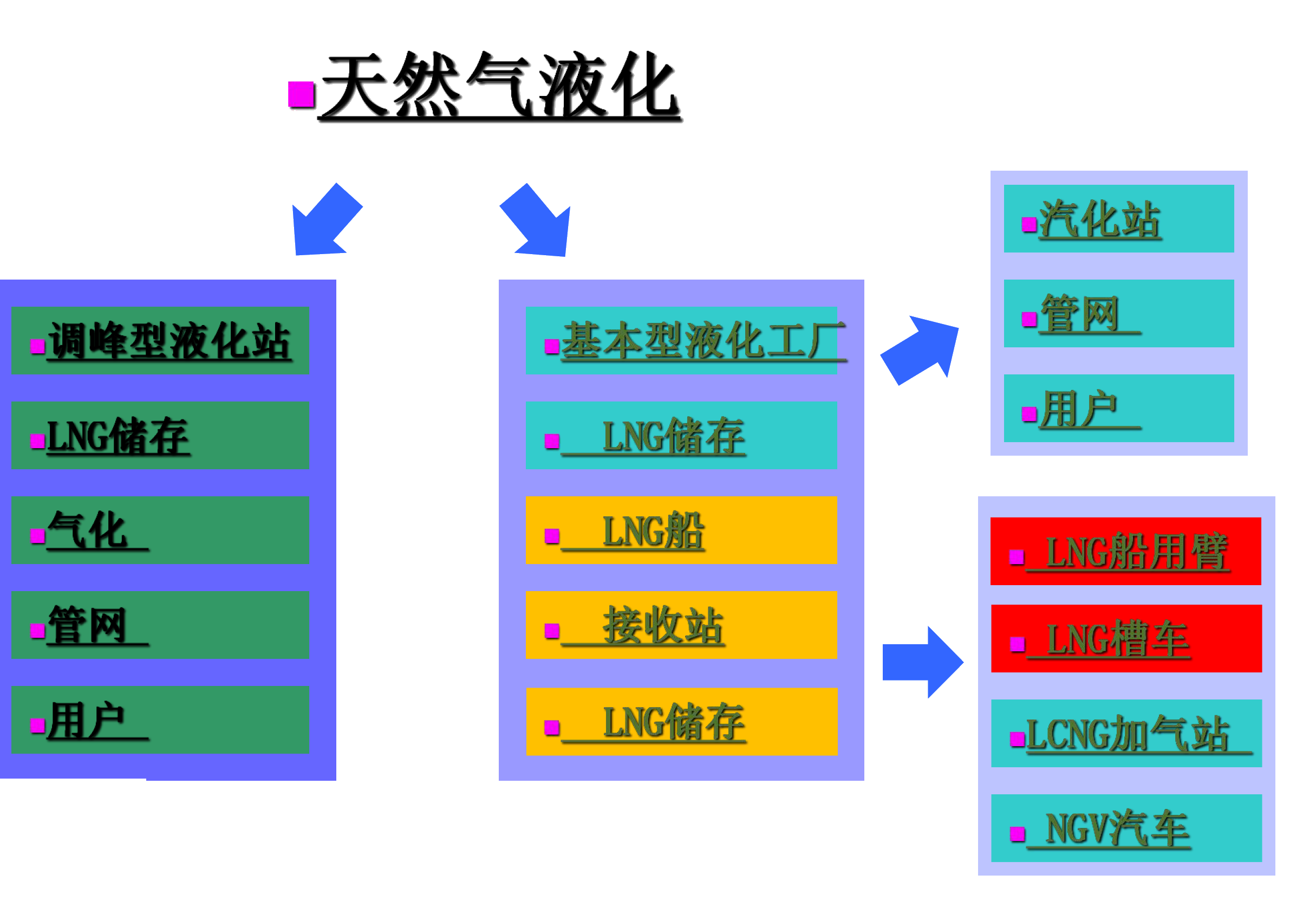
Natural Gas Liquefaction
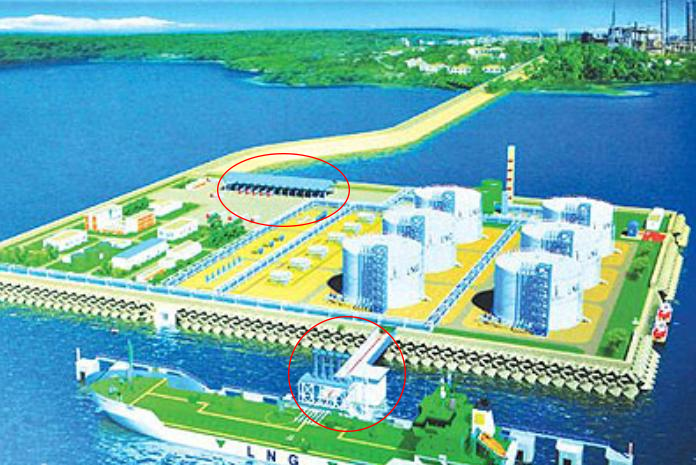
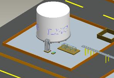
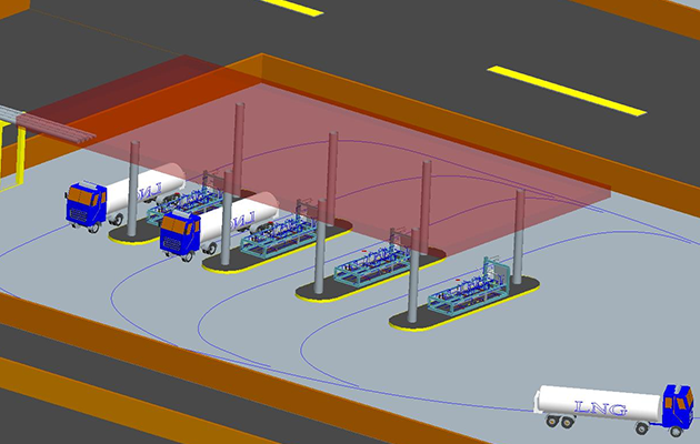
LNG receiving station renderings
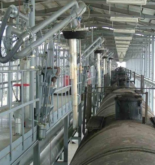
At present, LNG is mainly transported by LNG ships and LNG tank trucks. LNG is unloaded from ships to LNG storage tanks using LNG ship arms (as shown in Figure 1). LNG is filled from station tanks to LNG tank trucks using LNG pump skids (storage tank area) and LNG loading skids (loading area).
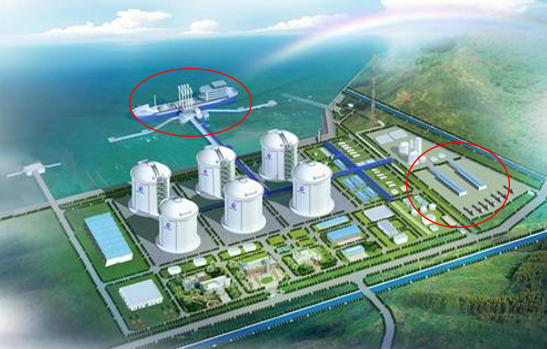
As shown in the LNG storage and transportation layout diagram, we can intuitively see the entire loading process of LNG from the storage tank through the pump skid, then through the pipeline corridor, and finally to the loading skid to fill the LNG tank truck.
LNG loading area
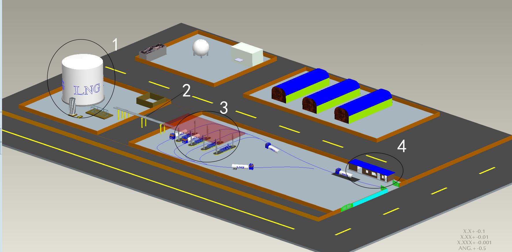
1.LNG storage tank area
2. LNG pipeline corridor
3.LNG loading area
4. Loading control room, guard room, loading waiting room, toilet
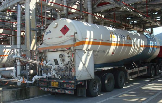
● In the LNG tank area, an integrated pump skid is used to pump LNG from the tank to the
● LNG loading area.
● In the LNG loading area, LNG is filled into the LNG tank truck using an integrated loading skid, and then invoiced, measured and settled in the control room.
● LNG pump skids and LNG loading skids are used in the LNG tank area and loading area respectively. Compared with laying pipelines on site, this makes the entire LNG storage and transportation
● The construction and commissioning cycle and production and operation costs of the transmission station are greatly reduced.
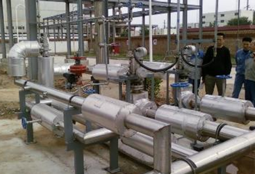
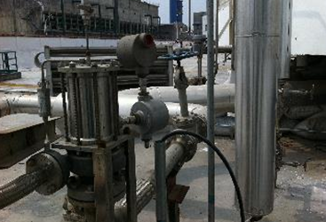
● The following figures show the situations of using on-site piping and pump skid.
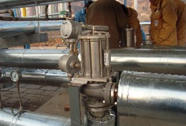
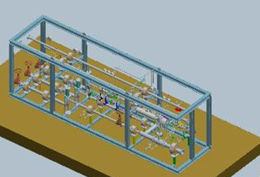
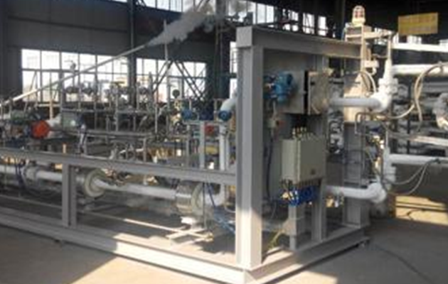
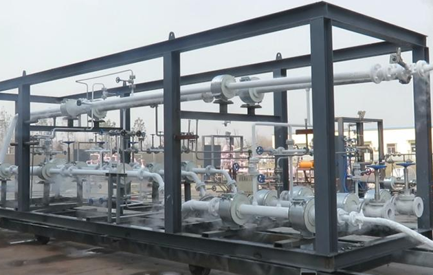
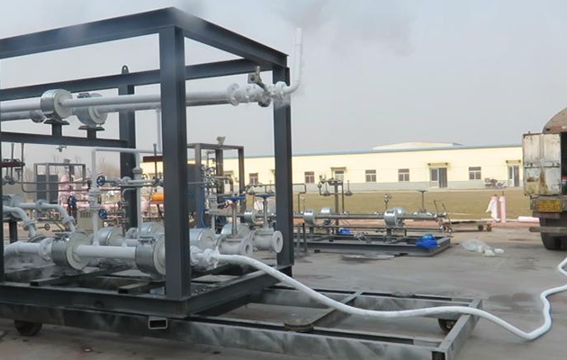
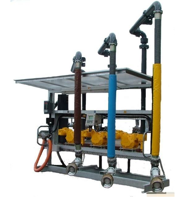
LNG loading area--Introduction to loading skid
The main function of the LNG loading skid is to quantitatively load liquefied natural gas tankers. The LNG loading skid mainly combines cryogenic cranes, automated control instruments, computer control technology, communication technology, etc., and integrates each module within a certain range of the skid frame. This reduces the labor intensity of workers in actual operation and saves space occupied by equipment; and the complete set of loading skids undergoes a series of tests (such as air tightness test, strength test, low temperature test, power-on commissioning test, etc.) before leaving the factory to ensure the stable performance of the loading skid, high safety, convenient operation and maintenance, and automation and intelligence.
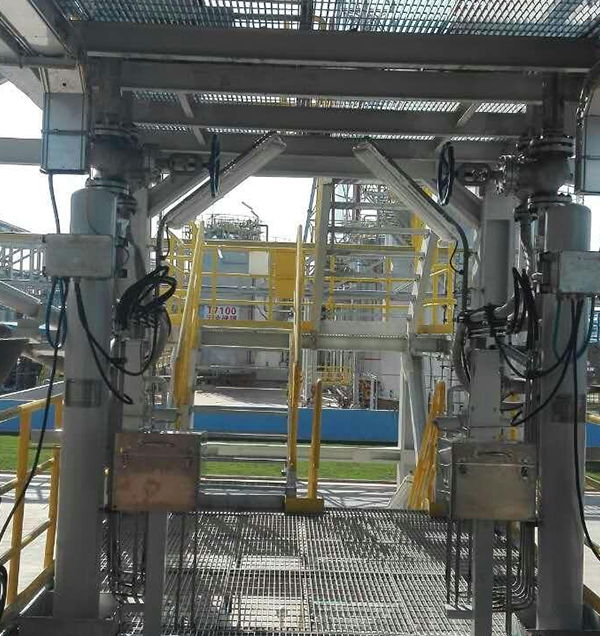
LNG loading area
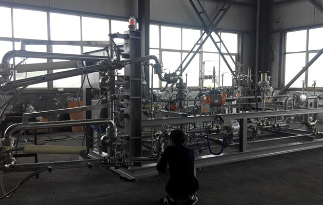
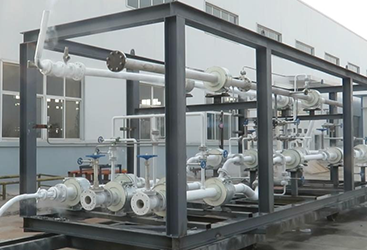
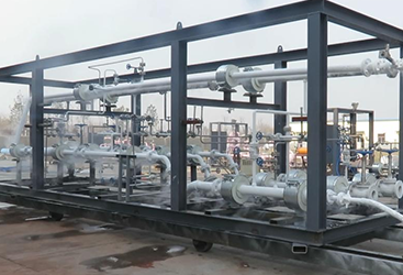
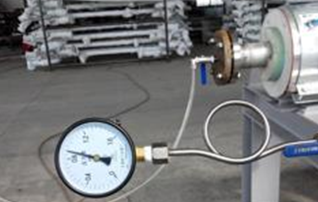
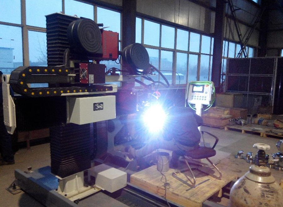
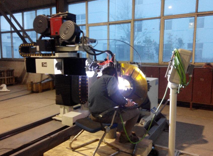
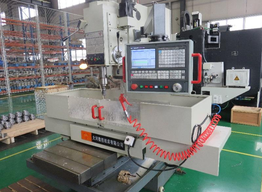
In-plant testing of pump skids and loading skids
The LNG loading skid and pump skid are equipped with instruments and electrical installation in the factory, with good production conditions, good welding and installation quality; the carbon steel parts are sandblasted, the paint environment is good, and the anti-corrosion performance is good. The factory also conducts airtightness test, strength test and low temperature test, which are sometimes difficult to be fully completed on site, and the product quality is guaranteed.
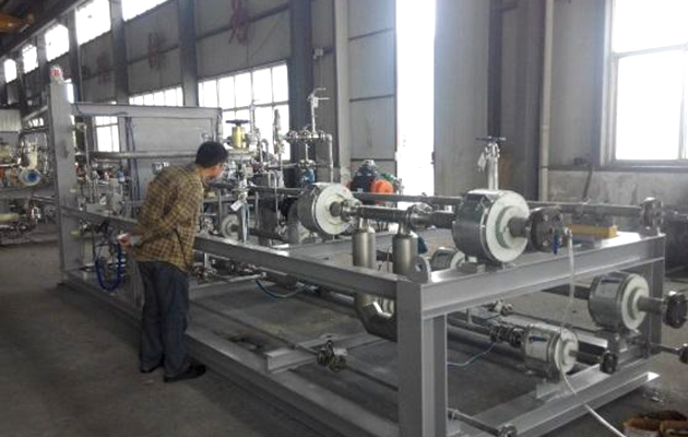
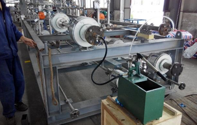

The pipeline welds in the equipment are welded by fully automatic argon arc welding. After welding, the welds are subjected to non-destructive testing to ensure the quality of pipeline welding.

LNG loading arm
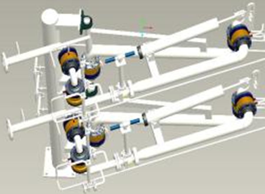
Brief description of cryogenic crane structure
● The cryogenic crane is specifically called the cryogenic land-based fluid loading and unloading arm, which is a device specially used for loading and unloading liquefied natural gas tank trucks with cryogenic media. The equipment consists of a column, a liquid phase arm, a gas phase arm (both the liquid phase arm and the gas phase arm include an inner arm, an outer arm, a balancing mechanism, and an outrigger arm with an American OPW emergency breakaway valve), a rotary joint nitrogen lubrication system, an electrostatic conductive belt, a nitrogen replacement system, etc.
● The liquid phase arm and the gas phase arm are arranged side by side, and the two have similar structures and can be operated independently. A low-temperature ball valve for loading is installed near the inner arm end of the outer arm, and a replacement purge device is installed at the front end of the low-temperature ball valve. The inner arm and the column, the outer arm and the inner arm, and the outer arm and the outer arm are all connected through a low-temperature rotary joint, and the low-temperature rotary joint is equipped with a nitrogen purge system. Nitrogen purge can directly bring out the water vapor in the rolling track, keep the rotating joint rolling track dry, and prevent damage to the rotating joint rolling track due to water vapor freezing.
● The low-temperature ethane unloading crane pipe rotating joint is made of 316L material, and the pipeline system is made of 304L material. It is treated with a deep cold process and welded using a special welding process. Strength, sealing and low-temperature tests are carried out on each unit to fully ensure the reliability of various performance of the equipment.
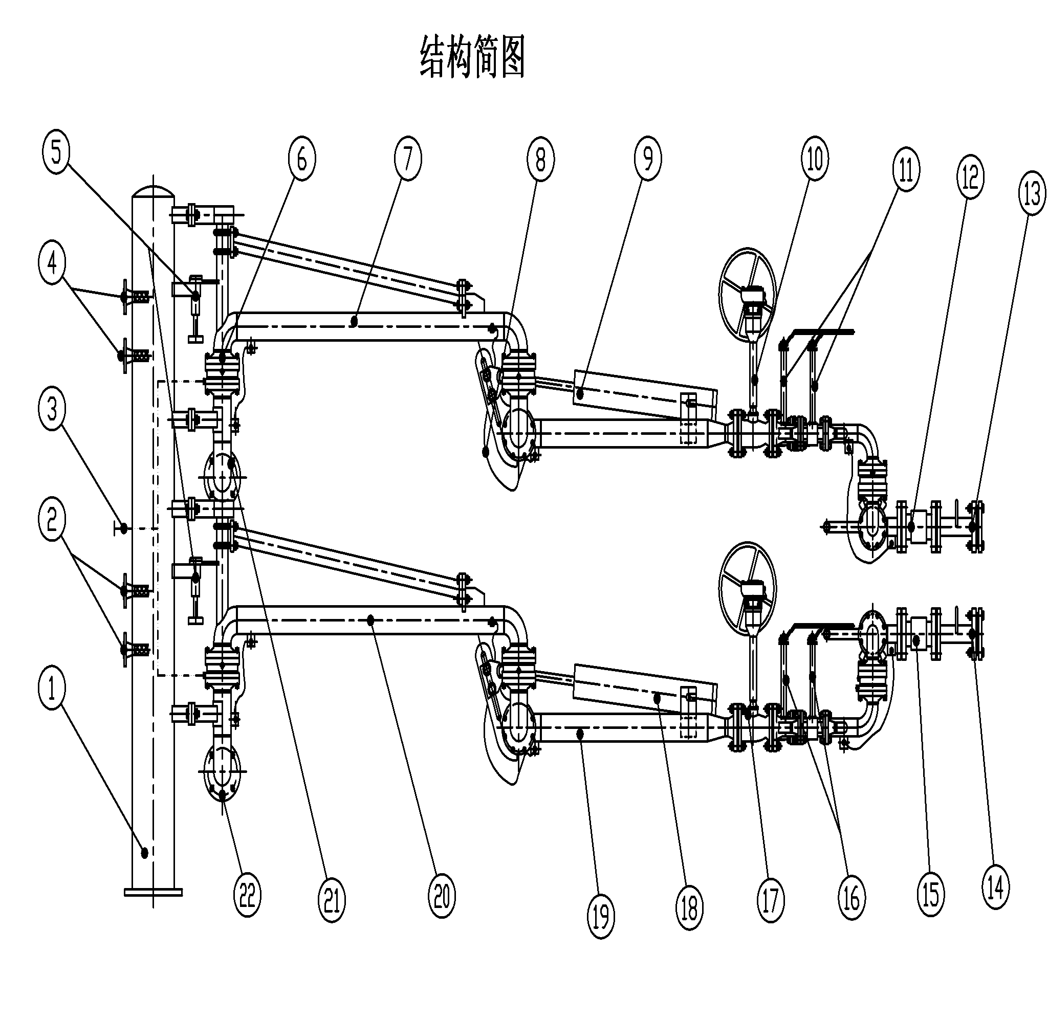 1. Column
2. Liquid phase arm nitrogen purge replacement pipeline
3. Rotary joint nitrogen purge pipeline
4. Gas phase arm nitrogen purge replacement pipeline
5. Gas phase and liquid phase inner arm locking device
6. Low temperature rotary joint
7. Gas phase inner arm
8. Static Conductive Belt
9. Gas phase outer arm balancing device
10. DN50 gas phase outer arm ball valve
11. DN25 gas phase purge replacement cryogenic ball valve
12. Gas phase arm breakaway valve
13. Gas phase arm vertical pipe section (DN50)
14. Liquid phase arm vertical pipe section (DN50)
15. Liquid arm breakaway valve
16. DN25 liquid phase purge cryogenic ball valve
17. DN50 liquid phase outer arm ball valve
18. Liquid phase outer arm balancing device
19. Liquid phase outer arm
20. Liquid phase inner arm
21. Gas phase arm inlet flange
22. Liquid phase arm inlet flange
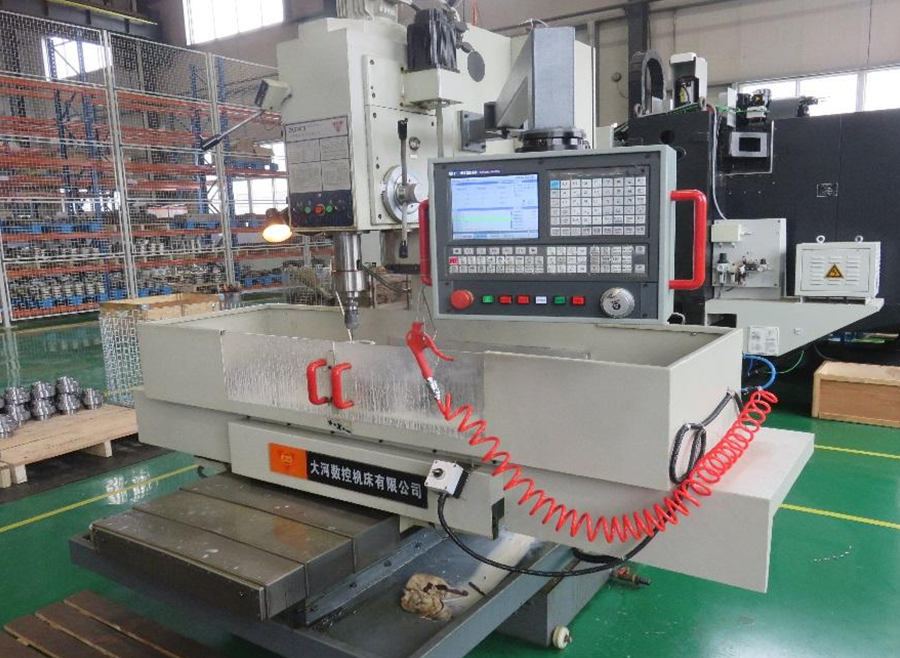
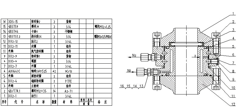
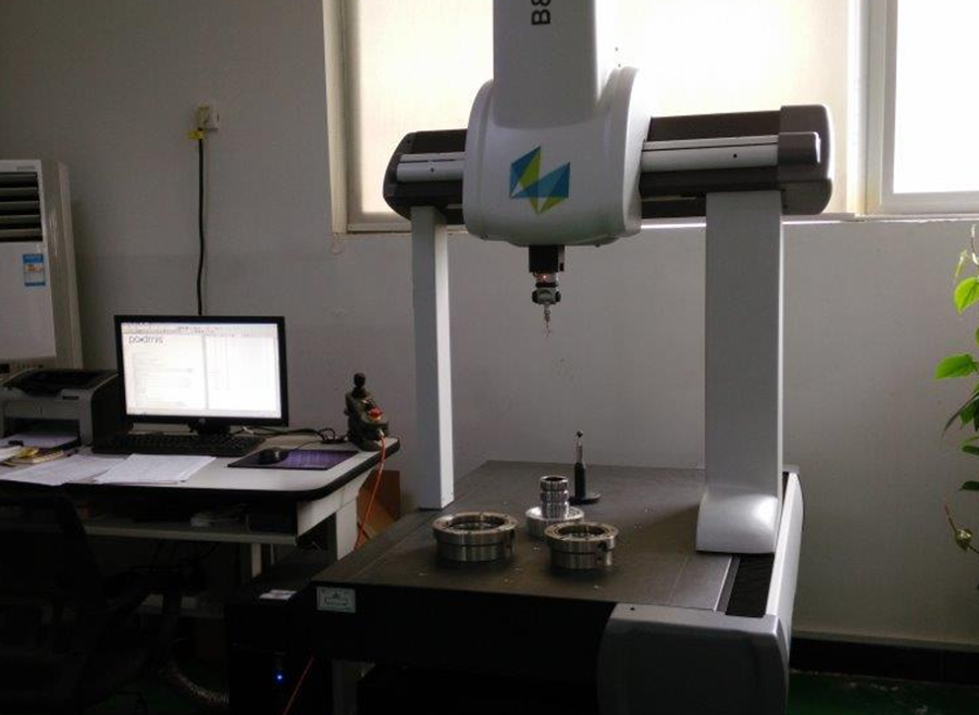
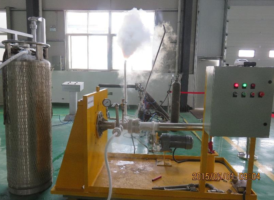
Processing, inspection and testing of low temperature rotary joints
● Our company's low-temperature rotary joints use advanced processing and testing equipment, and the assembled rotary joints are subjected to low-temperature dynamic load tests (according to specifications BSEN1474; OCIMF; HG/T 21608) to ensure the quality of the low-temperature rotary joints and their safety during on-site use.
● The processing, testing, welding and testing equipment used by our company are in the leading position in the industry.
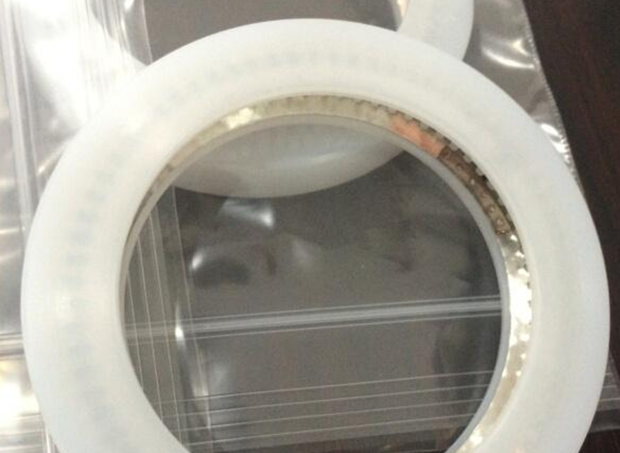
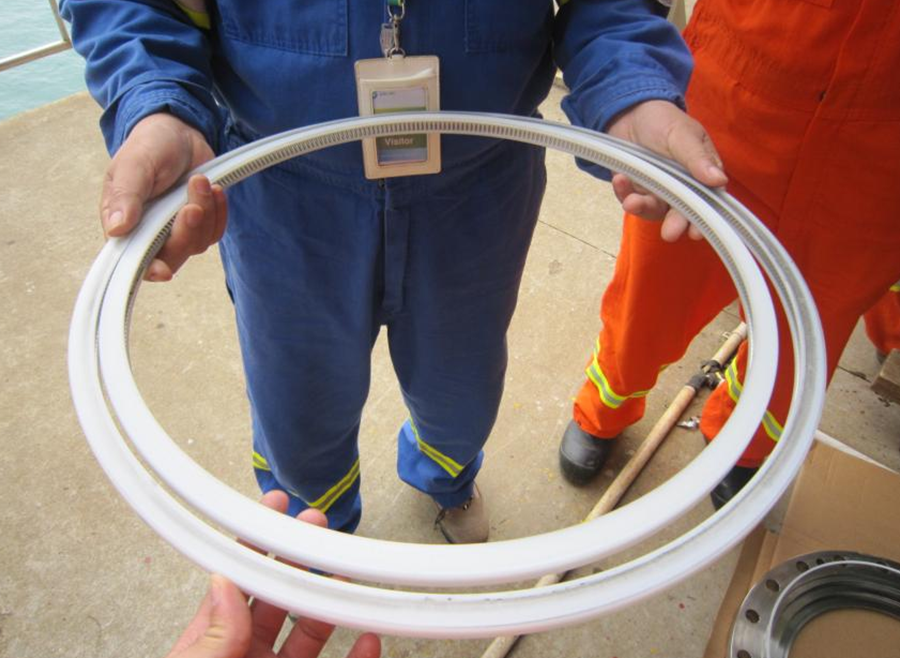
Low temperature rotary joint
The swivel joint is the core component of the loading arm. The quality assurance of the swivel joint directly determines the performance and life of the entire cryogenic loading arm. See the figure below - cross-section of the swivel joint for the cryogenic arm.
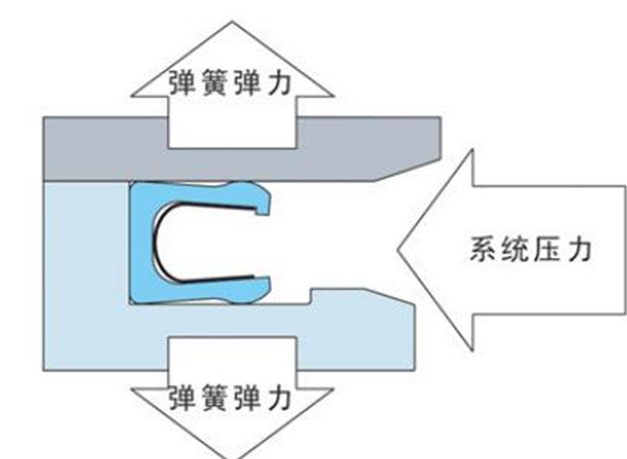
High performance low temperature seal
● Sealing shell material:
Modified PTFE; Ultra-high molecular weight polyethylene; UHMWPE;
● Materials commonly used for sealing springs:
304 stainless steel, 316 stainless steel, inconel alloy, Elgiloy alloy, Hastelloy nickel-based alloy
● Temperature range:
-268°C to 420°C;
● Pressure application range:
0 to 5500 Bar (80000 PSI)
Through the above introduction to the LNG station storage and transportation system, the station loading system using pump skids, loading skids, and loading and unloading arms has the following main advantages:
1. The need for modular design
At present, it only takes 2 to 3 years for an LNG station to be designed and put into use, and the design department only has one year. The common way to do this in a short period of time is to adopt a modular design approach, combining some independent functional parts into a module, and having the supporting manufacturers complete the internal detailed design and production. The loading system of the LNG storage and transportation station has created a demand for pump skids and loading skids, and the modularity of the loading system is the pump skids and loading skids.
2. Quality is guaranteed
LNG pump skids, loading skids, and marine arms are equipped with instruments and electrical installations in the factory. Good production and processing conditions mean good welding, installation, and testing quality. Carbon steel parts are sandblasted, and the paint spraying environment is good, which means good anti-corrosion performance. The factory also carries out air tightness tests, strength tests, low temperature tests, and power-on commissioning tests. These tests are sometimes difficult to be completed on site, but can be done well in the factory, which ensures product quality.
3. Shorten the construction and commissioning period
Factory production, commissioning and trial run are completed, and any problems that arise can be solved immediately. It can be carried out simultaneously with on-site infrastructure construction and is not affected by various factors such as weather, on-site environment, personnel arrangements, and construction schedules. The skid can be put into use a few weeks after arriving at the site.
4. Good economy and guaranteed service
Manufacturing in the factory has low labor costs, less material consumption and waste, and relatively small testing costs. The total cost is much lower than direct on-site construction. The service is fully responsible by the manufacturer of the skid-mounted system and the service is timely. On-site pipe laying is the responsibility of the contractor and its sub-suppliers, which is prone to wrangling and untimely service.

Previous Page
Next Page
Contact Us
Address: 2000 Weiqing East Road, Jinshan District, Shanghai
Telephone: 86 21 57941569 86 13917958831
Fax: 86 21 57262601
E-mail:info@china-eminent.com
Social Media


Friendship Link